|
UPN PROFILE
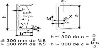
CONICAL FLANGE U PROFILE TS 912, DIN 1026
|
 |
|
Short
Sign
U
|
Dimensions
|
Section Area
|
Weight
|
Total Surface Area
|
For tilt axis 2)
|
3)
|
4)
|
x-y between the axis
|
5)
|
|
X-Y
|
Y-Y
|
Sx
|
Sx
|
|
|
|
|
h
|
b
|
s
|
t
|
r1
|
r2
|
F
|
G
|
S
|
ix
|
Wx
|
ix
|
iy
|
Wy
|
iy
|
|
|
ey
|
Xm
|
|
|
|
|
1)
|
|
|
cm2
|
kg/m
|
m2/m
|
cm4
|
cm3
|
cm
|
cm4
|
cm3
|
cm
|
cm3
|
cm
|
cm
|
cm
|
|
65
|
65
|
42
|
5.5
|
7.5
|
7.5
|
4
|
9.03
|
7.09
|
0.273
|
57.5
|
17.7
|
2.52
|
14.1
|
5.07
|
1.25
|
-
|
-
|
1.42
|
2.60
|
|
80
|
80
|
45
|
6
|
8
|
8
|
4
|
11.0
|
8.64
|
0.312
|
106
|
26.5
|
3.10
|
19.4
|
6.36
|
1.33
|
15.9
|
6.65
|
1.45
|
2.67
|
|
100
|
100
|
50
|
6
|
8.5
|
8.5
|
4.5
|
13.5
|
10.6
|
0.372
|
206
|
41.2
|
3.91
|
29.3
|
8.49
|
1.47
|
24.5
|
8.42
|
1.55
|
2.93
|
|
120
|
120
|
55
|
7
|
9
|
9
|
4.5
|
17.0
|
13.4
|
0.434
|
364
|
60.7
|
4.62
|
43.2
|
11.1
|
1.59
|
36.3
|
10.0
|
1.60
|
3.03
|
|
140
|
140
|
60
|
7
|
10
|
10
|
5
|
20.4
|
16.0
|
0.489
|
605
|
86.4
|
5.45
|
62.7
|
14.8
|
1.75
|
51.4
|
11.8
|
1.75
|
3.37
|
|
160
|
160
|
65
|
7.5
|
10.5
|
10.5
|
5.5
|
24.0
|
18.8
|
0.546
|
925
|
116
|
6.21
|
85.3
|
18.3
|
1.89
|
68.8
|
13.3
|
1.84
|
3.56
|
1) Allowable plus tolerance is limited by weigh tolerance
2) I= moment of inertia , W=moment of resistance, i=radius of gyration, which belogs to tilt axis.
3) Sx=1x:Sx=Push and pull away from the midpoint.
4) Xm=M Shear Mid-pıinted the distance to the axis of y-y. Weight section, surface areas and static values are calculated acoording to dimensions shown in the table.